
A finite state machine (FSM) is a sequential circuit described by a finite set of states, input signals, transitions, and outputs. The current state summarizes relevant history from the input sequence. On an active clock edge, the machine uses its state and inputs to choose a next state.
Next-state and output logic
An FSM has next-state logic and output logic. The next-state function is state⁺ = f(state, input). The output function depends either on state alone or on both state and input. Flip-flops store the state; combinational logic calculates transitions and outputs.
Moore machine
In a Moore machine, outputs depend only on current state: output = g(state). Outputs change when the state register changes, normally just after a clock edge. This often makes outputs stable and easier to use, though a Moore design may need an extra state to represent an output event.
Mealy machine
In a Mealy machine, outputs depend on current state and current inputs: output = g(state, input). The output can respond during a clock cycle as soon as an input changes and the combinational logic settles. This can reduce state count or response latency, but input glitches can also appear at the output unless handled carefully.
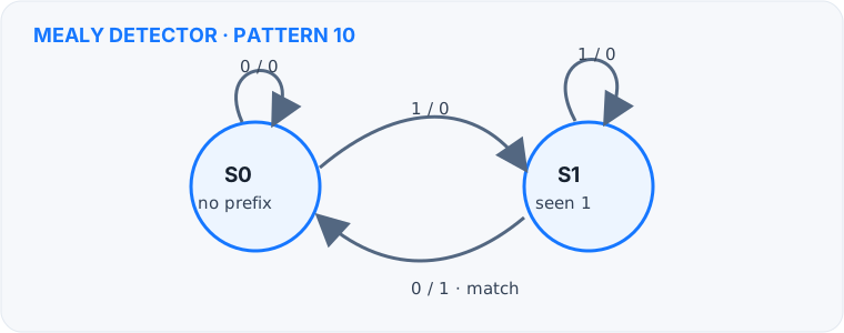
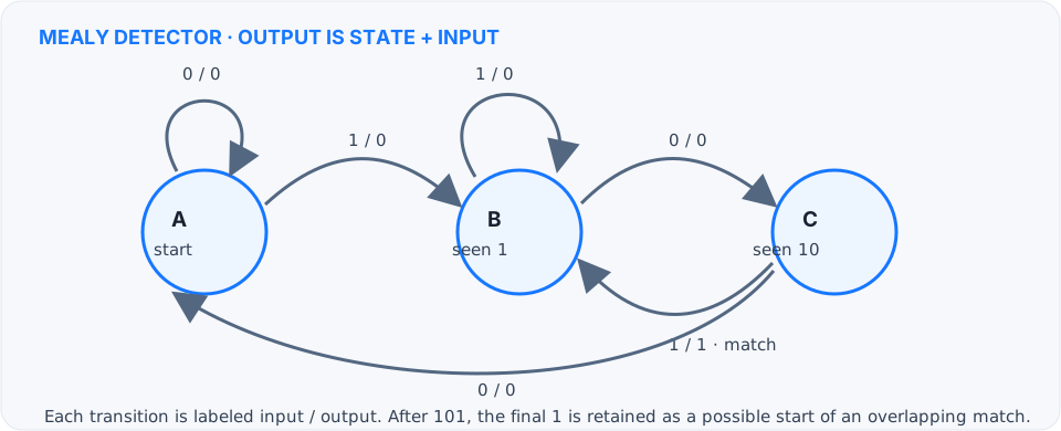
Mealy diagrams: detecting 10 and 101
Transition labels use input / output. The output is produced on the transition that completes the pattern, and the machine can retain a useful suffix for overlapping matches.
Compare the two models
| Property | Moore | Mealy |
|---|---|---|
| Output depends on | Current state | Current state and input |
| Typical output change | After a state transition | After state or input changes |
| State count | May require more states | Often fewer states |
| Input-to-output path | No direct combinational path | Can respond within a cycle |
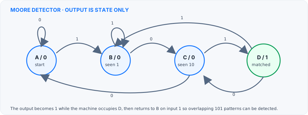
Moore diagram for the same pattern
Example: detecting the sequence 10
States can represent how much of the pattern has been seen: no useful prefix, a trailing 1, and a completed 10. A Moore detector asserts its output in the completed state. A Mealy detector can assert on the transition that receives 0 while in the “seen 1” state. Both detect the same sequence, but their output timing and state diagrams differ.
A practical design workflow
- Write the required behavior and identify what history must be remembered.
- Name each state and explain what it represents.
- Draw transitions for every input condition, including overlap cases.
- Choose Moore or Mealy output rules and label outputs clearly.
- Encode states, derive next-state logic, then verify every transition with a table or simulation.
Choose Moore when predictable state-based outputs are the priority. Choose Mealy when an immediate input response or smaller state graph matters, and check output timing carefully.