
Inputs, outputs, and truth tables
Logic gates are the basic building blocks of digital circuits. They take binary inputs and produce an output according to a fixed truth table. Combined in larger networks, gates can implement complex computations.
AND, OR, and NOT
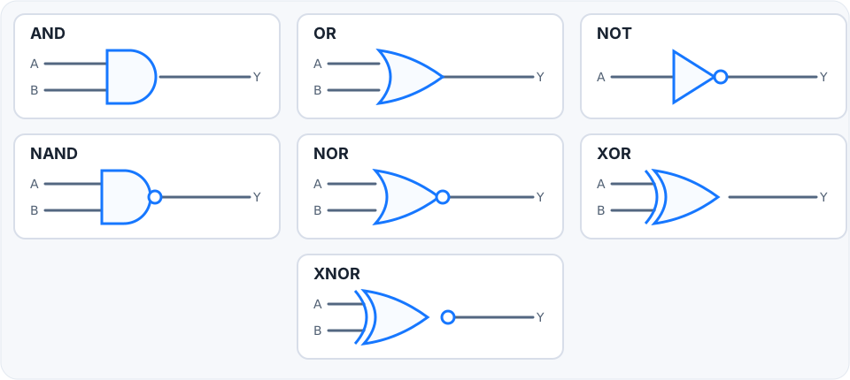
A NOT gate flips an input. AND is true only when all inputs are true; OR is true when at least one input is true. These operations form the foundation for reading Boolean expressions and circuit diagrams.
NAND, NOR, XOR, and XNOR
NAND and NOR invert the result of AND and OR. XOR is true when its inputs differ; XNOR is true when they match. XOR and XNOR are useful in parity checks, comparators, and arithmetic circuits.
Translate a circuit into logic
Each gate is a compact way to express a Boolean function. Read a circuit from inputs toward the output, writing an expression for each gate as you go. This makes larger designs easier to understand.
Learn by testing every input
Experiment with inputs and observe the output. A simulator turns abstract rules into visible behavior and helps verify that your understanding matches the truth table.
Logic gate symbols at a glance
Core truth tables
| A | B | AND | OR | XOR | NAND |
|---|---|---|---|---|---|
| 0 | 0 | 0 | 0 | 0 | 1 |
| 0 | 1 | 0 | 1 | 1 | 1 |
| 1 | 0 | 0 | 1 | 1 | 1 |
| 1 | 1 | 1 | 1 | 0 | 0 |
How to read the gates
AND is 1 only when every input is 1 (Y=A·B). OR is 1 when at least one input is 1 (Y=A+B). NOT complements one input (Y=Ā). XOR is 1 when its inputs differ (Y=A⊕B), while XNOR is 1 when they match. NAND is the inverse of AND and NOR is the inverse of OR. For more than two inputs, apply the same rule across all inputs.
Universal gates
NAND and NOR are called universal because either one alone can build NOT, AND, OR, and therefore any Boolean function. For example, a NAND used with both inputs tied together gives an inverter: Ā = NAND(A,A). Invert the output of NAND to get AND: AB = NAND(NAND(A,B), NAND(A,B)). This matters in hardware because a design can be implemented using a single available gate family.
From a requirement to a circuit
Translate the requirement into input cases, write a truth table, then derive an expression for the rows where the output should be 1. For example, “turn on when A and B are both active” gives Y=A·B, so one AND gate is enough. “Turn on when either sensor detects a signal” gives Y=A+B. Use the simulator to check every row before relying on a circuit.